Google

Thursday, August 04, 2005

Restrained Shrinkage Model

I've been putting my efforts into developing my finite element model that simulates the behavior of the restrained shrinkage models constructed and tested by Radabaugh (Radabaugh, 2001). The specimens were 9' by 9' reinforced slabs constructed fully composite with W12x65 girders. Radabaugh construced two specimens whose only difference was in the type of formwork that was used in construction. The specimens were reinforced with #4 and # 5 bars spced at 12" in the longitudinal direction and at 8" in the transverse direction. The specimens are shown below.


I modeled the specimen using ANSYS. The concrete was modeled using SOLID65 nonlinear concrete elements, the reinforcement was modeled using LINK8 elements, and the girders were modeled using SHELL63 elements. Also, the specimens were constructed with diaphrams at the supports. These were modeled using BEAM4 elements. The model is shown in the figure below.

A quick note of interest concerning the use of shell elements for modeling girders. I initially used shell elements which did not have a DOF for in-plane membrane forces. When the analysis was run, the simulation did not behave correctly (i.e. girders appeared to "hinge" out of plane and did not exhibit propoer flexural behavior). Obviously, in-plane forces are how girders carry flexure. Thus, be sure to use shell elements that have membrane force capabilities when using shells to model girders.


Wednesday, July 20, 2005

Cracking Concrete Virtually

I have been spending alot of my time recently, trying to ensure that the model will simulate cracking correctly. I began by using a simple fixed-fixed model, as shown below. The model uses ANSYS SOLID65 nonlinear concrete solid elements to model the concrete and LINK8 3D spar elements to model a single piece of reinforcement. The reinforcement is modeled deiscretely rather than using the SOLID65 element's smeared reinforcement option.


Since the finite element model cannot explicitly impose shrinkage strains, the thermal coefficient of expansion is used and by applying body temperature loads to the model, shrinkage of the concrete can be simulated. The model has a coeffiecient of thermal expansion of 6 x 10^-6 for concrete and zero for the reinforcing steel. The steel's coeffiecient is given a value of zero to simulate the fact that steel does not shrink due to moisture loss. As the model becomes more sophisticated and thermal effects are considered in combination with drying shrinkage, an adjusted coefficient of thermal expansion will have to be used. A temperature change of 50 F is applied to the model. This corresponds to a shrinkage strain of 300 microstrain. The figure below shows the stress in the model in the long dimension of the specimen. Stresses are uniform along the length of the specimen, expecept at the ends where the boundary conditions induce stress concentrations.

After observing the stresses in the model, the locations of the cracks are plotted. The following two figures show the cracks plotted by ANSYS. All cracks form at the ends of the specimen, in the regions affected by the stress concentrations from the applied boundary conditions.

Tuesday, June 28, 2005

Poisson's Ratio

I came across an interesting problem while doing some preliminary models. I was modeling a cantilever member (10" x 10" x 60"). I had fixed the nodes at one end for all DOFs and applied a temperature change of 50 F. One would expect the stress in the member to be uniform and approximately zero. However, the plot of the stresses in the long dimension of the member showed there to be some variation in the stresses given by the model.


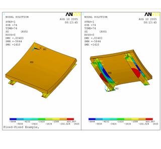
Note that the red contour indicates stresses between 0.1 and 1 psi. The gray contours are stresses greater than 1 psi. While high stresses should be expected near the support, such areas of higher stress at a distance of 16 in. away from the support was unexpected.

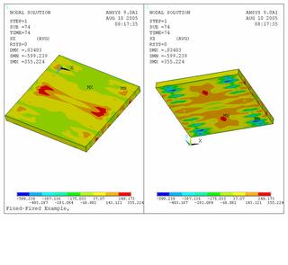
Since Poisson's effects were suspected as the cause for the variation in stresses, the boundary conditions were changed to the arrangement shown below. Only the center four nodes at the end were restraned in all DOFs. The rest were only restrained in the Z-direction (long dimension of the model).


The analysis was run again with the new BCs and the same temperature load applied. The stresses in the model were found to be more consistent as well as clloser to the correct value of zero.


Note that with the improved BCs, the model only gives stresses above 1 psi within 12 in. of the end support. This is consistent with St. Venant's principle which states that at a distance b away from the load stress are uniform, where b is the width of the section being loaded. Points within a distance b exhibit higher stresses and the stresses are not uniformly distributed (Beer & Johnston 1992).

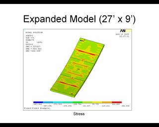
We can see then that poisson's ratio is significantly effecting the results derived from the model. Thus, I set Poisson's ratio equal to zero and repeated the analysis. The stresses at a section through the middle of my model specimen are shown below. The stresses observed are now significantly more uniform and are generally closer to zero.

Thursday, June 16, 2005

References

I thought it best to make a post that would contain assorted references. I'll post references as I use them on the site in the comments in this post. As an aside here, I'll only post the references that I make mention to on this site. If you feel that there is a reference that you feel I should consider/mention/look into, please drop it into the comments under this post.

First Steps...Free Shrinkage Models

Within the comments of this post I'll discuss my free-shrinkage modelling efforts. Using ANSYS I made models of laboratory specimens used as a part of the work by David Blackman (Blackman 2002). See the comments for more details, to drop in your opinion, or to tell me I'm completely wrong.


*Note* I will be adding content to the comments over time, so be sure to check back from time to time if something interests you.

Tuesday, June 14, 2005

Example of the effects of restrained shrinkage

Transverse crack likely caused by restrained shrinkage of the concrete deck by the steel girders

Posted by Hello
Photo taken by Jacob Bice (2003)

The Problem So Far...

Naturally, the first question is, "Why try to model restrained shrinkage of concrete?" It is a well established fact that concrete shrinks and because of restraint subsequently cracks. Concrete design codes have addressed control of shrinkage cracks since the 1920s. Current code design provisions are essentially unchanged since the 1940s. However, the codes in their present state are:

1) Entirely based upon empirical observation
2) Address only the case of unrestrained shrinkage
3) Do not give specific guidance concerning the restrained shrinkage case

Thus the goal of my work has been to develop design recommendations based upon my experimental and analytical work.

Opening

I created this site to document my efforts at finite element analysis of concrete bridge decks. Specifically, I am interested in modeling the restrained shrinkage of the decks and determining the the effect on global behavior of various design characteristics of the bridges. This work is apart of my dissertation research and is ongoing. This site is by no means an "expert" site but rather an arena in which I can deposit some of the fruits--small though they may be--of my labors. Furthermore, I welcome any comments, suggestions, criticisms, and/or ecouragement anyone with expertise or knowledge in this area may have to offer.