Restrained Shrinkage Model
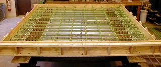
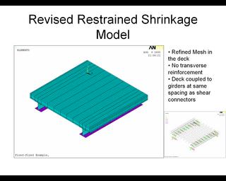
I modeled the specimen using ANSYS. The concrete was modeled using SOLID65 nonlinear concrete elements, the reinforcement was modeled using LINK8 elements, and the girders were modeled using SHELL63 elements. Also, the specimens were constructed with diaphrams at the supports. These were modeled using BEAM4 elements. The model is shown in the figure below.
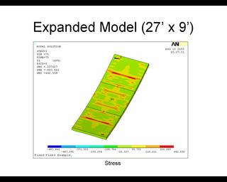
A quick note of interest concerning the use of shell elements for modeling girders. I initially used shell elements which did not have a DOF for in-plane membrane forces. When the analysis was run, the simulation did not behave correctly (i.e. girders appeared to "hinge" out of plane and did not exhibit propoer flexural behavior). Obviously, in-plane forces are how girders carry flexure. Thus, be sure to use shell elements that have membrane force capabilities when using shells to model girders.
posted by Erin and Jake at 8:57 AM
2 comments
![]()

